 English
 русский
 Deutsch
News
Home / News / Industry News / The Ultimate Guide to Air Cooled Capacitors: Selection, Benefits, and Maintenance
Content
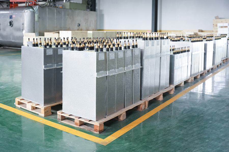
In the realm of electrical engineering and power systems, capacitors play an indispensable role in managing power flow and improving efficiency. Among the various types available, the air cooled capacitor stands out for its specific design and application. Unlike liquid-cooled counterparts, these capacitors rely on the natural or forced circulation of air to dissipate heat generated during operation. This fundamental cooling mechanism makes them particularly suited for environments where simplicity, reliability, and avoidance of liquid coolant leaks are paramount. They are essentially passive electronic components that store and release electrical energy, but with an integral design that prioritizes heat dissipation through air flow, ensuring stable performance and longevity in circuits that experience significant current loads.
The core function of any capacitor is to oppose changes in voltage by storing and releasing energy from its electric field. However, under continuous operation, especially in high-power applications like motor run circuits, power factor correction units, and high-frequency inverters, capacitors can generate considerable internal heat due to resistive and dielectric losses. This heat, if not effectively managed, can lead to premature degradation of the dielectric material, evaporation of the electrolyte, and ultimately, catastrophic failure. This is where the design of an air cooled capacitor becomes critical. Its construction often includes features like extended metallic surfaces (fins), open-frame designs, or strategic placement within an equipment enclosure to maximize surface area exposed to cooling air. This design efficiently transfers thermal energy from the capacitor's core to the surrounding air, maintaining operating temperatures within safe limits prescribed by manufacturers.
The advantages of this approach are multifaceted. Firstly, it eliminates the complexity and potential failure points associated with pumps, hoses, and radiators found in liquid cooling systems. Secondly, it reduces maintenance requirements, as there is no need to monitor coolant levels or worry about fluid degradation over time. Furthermore, air cooling is inherently safer in sensitive environments where a leak of liquid coolant could cause electrical shorts, corrosion, or environmental contamination. Therefore, understanding the principles behind air cooling is the first step in appreciating why these components are the preferred choice in a wide array of industrial and commercial applications.
To fully grasp how an air cooled capacitor operates, it is essential to deconstruct its anatomy. While designs vary between manufacturers and specific applications, several key components are common across most units.
At the heart of every capacitor is the element, which consists of two conductive plates separated by a dielectric insulating material. In film capacitors, which are common in air-cooled designs, the plates are metallic foils and the dielectric is a thin plastic film. This assembly is wound into a cylindrical roll. The type of dielectric material (e.g., Polypropylene, PET) significantly influences the capacitor's key characteristics, including its capacitance value, voltage rating, and maximum operating temperature.
This is the defining feature of an air cooled capacitor. Typically made from aluminum, a material known for its excellent thermal conductivity, these fins are mechanically attached to the capacitor's canister or the element itself. Their primary function is to drastically increase the surface area available for heat transfer. As air passes over these fins, heat is carried away from the capacitor body through convection. The design of the fin pattern—its density, height, and shape—is optimized to create turbulent air flow, which enhances heat dissipation efficiency without creating excessive air flow resistance.
The internal element is housed within a protective metal canister, usually aluminum. This canister provides mechanical protection, contains the internal components, and serves as a base for mounting the cooling fins. In some designs, the housing itself may be finned. The unit is hermetically sealed to prevent the ingress of moisture and contaminants, which could compromise the dielectric strength and lead to internal short circuits.
Robust terminals, designed to handle high currents without overheating, provide the electrical connection points. These are often threaded studs or heavy-duty solder lugs, ensuring a secure and low-resistance connection to the external circuit, which is crucial for maintaining efficiency and preventing localized heating at the connection points.
Selecting the appropriate air cooled capacitor is a critical decision that impacts the efficiency, reliability, and lifespan of your electrical system. A poorly chosen capacitor can lead to system inefficiencies, frequent failures, and even safety hazards. The selection process involves a careful balance of several electrical and physical parameters to ensure optimal performance under specific operating conditions.
The first and most obvious parameter is the capacitance value, measured in microfarads (µF). This value must match the requirements of the application, whether it's for smoothing voltage, power factor correction, or motor starting/running. Selecting a value that is too low will result in inadequate performance, while a value that is too high can cause overcurrent conditions and damage other components. The second crucial parameter is the voltage rating. The capacitor's rated voltage must always be higher than the maximum expected voltage in the circuit, including any spikes or surges. A common rule of thumb is to choose a capacitor with a voltage rating at least 1.5 times the system's nominal operating voltage to provide a sufficient safety margin.
Equally important is the consideration of the current load. Capacitors, especially those used in power factor correction or AC motor run applications, carry significant alternating current. The capacitor must be rated to handle this current without excessive internal heating. This is where the advantages of air cooled capacitor for high current systems become a major selection factor. For high-current applications, an air-cooled design is often not just beneficial but necessary. Compared to a standard non-cooled capacitor of the same physical size, an air-cooled unit can typically handle much higher ripple currents because its finned design efficiently rejects heat. This prevents the internal hot-spot temperature from exceeding the limits of the dielectric material.
To illustrate the critical differences between a standard capacitor and an air-cooled capacitor in high-stress applications, consider the following comparison presented in both sentence and table form. A standard non-cooled capacitor relies on natural convection from its smooth casing for cooling, which limits its ability to dissipate heat, making it suitable only for low to medium current applications where heat generation is minimal. In contrast, an air cooled capacitor utilizes extended surfaces (fins) to dramatically increase heat transfer area, allowing it to safely handle the significantly higher thermal loads generated by high ripple currents, making it the indispensable choice for high-power inverters, induction heating, and heavy-duty power factor correction banks.
| Feature | Standard Non-Cooled Capacitor | Air Cooled Capacitor |
|---|---|---|
| Heat Dissipation Method | Natural convection from a smooth surface | Forced or natural convection from extended fin surfaces |
| Maximum Allowable Ripple Current | Relatively Low | High to Very High |
| Suitable Applications | Low-power electronics, light-duty motor run, filtering | High-power inverters, induction heating, furnace controls, heavy-duty PFC |
| Cost and Complexity | Lower cost, simpler design | Higher initial cost, optimized thermal design |
Other vital selection criteria include:
By meticulously evaluating these factors against your system's specifications, you can select an air cooled capacitor that delivers maximum performance, durability, and value.
The unique ability of the air cooled capacitor to handle significant thermal stress makes it the component of choice in a diverse range of demanding applications. Its robustness and reliability are leveraged wherever electrical systems generate substantial heat and where dependable operation is non-negotiable.
One of the most prominent applications is in power factor correction (PFC) capacitor banks. In industrial settings, large inductive loads like motors, transformers, and welding equipment cause a lagging power factor, which results in inefficient energy use and potential utility penalties. PFC capacitor banks are installed to counteract this lagging current and bring the power factor closer to unity. These banks often operate continuously and carry high currents, generating considerable heat. Air cooled capacitors are ideally suited for this role because their design prevents overheating, ensuring stable capacitance and preventing premature failure that would compromise the entire PFC system's effectiveness. Their use directly translates into improved energy efficiency and reduced electricity costs for factories and large commercial buildings.
Another critical application is in the realm of high frequency and induction heating systems. These systems, used for metal hardening, brazing, and melting, operate at frequencies ranging from several kHz to several MHz. The capacitors used in the resonant tank circuits of these systems are subjected to extremely high alternating currents and intense electromagnetic fields. The resulting heat generation is immense. Standard capacitors would fail almost instantly under such conditions. Air cooled capacitors, often with custom fin designs and sometimes used in conjunction with forced air from blowers, are essential for maintaining temperatures within safe operating limits, ensuring process stability and equipment uptime.
Furthermore, air cooled capacitors are indispensable in renewable energy systems, particularly in solar and wind power inverters. These inverters convert DC power from panels or turbines into grid-compliant AC power. The conversion process involves high-power switching electronics that generate significant heat and require robust DC-link and filtering capacitors. In large-scale solar farms or wind turbines, where inverters are mounted in enclosures and must operate reliably for decades with minimal maintenance, the use of air cooled capacitors provides the necessary thermal management and longevity. Their sealed construction also protects them from harsh environmental conditions like humidity and dust, which are common in such installations.
Other notable applications include:
In each of these applications, the common denominator is the need for a capacitor that can perform reliably under thermal duress, a challenge that the air cooled capacitor is uniquely designed to meet.
Proper installation and diligent maintenance are paramount to unlocking the full lifespan and reliability potential of any air cooled capacitor. Even the highest-quality component can fail prematurely if installed incorrectly or neglected. Adhering to a set of best practices ensures operational safety, maximizes efficiency, and prevents unscheduled downtime.
The installation process begins even before the capacitor is physically mounted. First, it is crucial to verify that the received capacitor matches the specifications ordered—checking the capacitance, voltage rating, and case size. Before installation, a quick visual inspection for any signs of damage during shipping, such as dented casings or compromised terminals, is essential. The mounting location must provide adequate clearance around the capacitor to allow for unimpeded air flow. Blocking the fins with other components or wiring defeats the purpose of the cooling design and will lead to overheating. Forced air cooling, if specified by the manufacturer, must be correctly oriented so that the airflow direction is across the fins, not parallel to them, for maximum heat exchange efficiency.
Electrical connections must be made with care. Terminals should be tightened to the manufacturer's specified torque value using the appropriate tools. Under-tightening can lead to high-resistance connections that arc, overheat, and damage the terminal. Over-tightening can strip threads or crack the terminal assembly. It is also good practice to use lock washers to prevent connections from loosening over time due to vibration and thermal cycling. Finally, ensure that the capacitor is properly grounded if required by the application and local electrical codes. A poor ground connection can be a safety hazard and lead to electromagnetic interference (EMI) issues.
A proactive maintenance schedule is the best defense against unexpected failure. The cornerstone of maintaining an air cooled capacitor is regular inspection. Maintenance personnel should periodically:
Furthermore, for critical applications, periodic electrical testing can be invaluable. Using a capacitance meter, measure the actual capacitance and compare it to the rated value. A significant deviation (often more than 5-10%) indicates degradation of the dielectric. Similarly, using an LCR meter, the Equivalent Series Resistance (ESR) can be measured. A rising ESR value is a strong indicator that the capacitor is aging and becoming less efficient, generating more heat for the same current load. Documenting these measurements over time provides a trend analysis that can predict end-of-life and allow for planned replacement during a scheduled shutdown, avoiding costly unplanned downtime. This comprehensive approach to maintenance ensures that the long lifespan of properly maintained air cooled capacitors is fully realized, protecting your investment and ensuring system integrity.
Despite their robust design, air cooled capacitors can experience issues. Recognizing the symptoms of a failing capacitor and understanding how to diagnose the root cause is a critical skill for ensuring system reliability and safety. Problems can manifest in both the capacitor itself and the system it serves.
One of the most common failure modes is a simple open circuit. The capacitor fails internally, breaking the electrical connection. The symptom in the circuit is often a complete loss of function for the stage the capacitor is part of. For example, a motor may fail to start, or a power supply may have excessive AC ripple on its output. A short circuit failure is less common but more dramatic. It occurs when the dielectric breaks down completely, connecting the two plates directly. This usually causes a very high current to flow, which will typically blow a fuse, trip a circuit breaker, or in severe cases, cause damage to other components like rectifiers or switching devices. The capacitor itself may show visible signs of distress, such as a ruptured vent or a bulging and discolored case.
More insidious than a complete failure is gradual degradation. The capacitor's capacitance may slowly decrease, or its Equivalent Series Resistance (ESR) may increase over time. This leads to a gradual decline in system performance rather than a sudden failure. Symptoms can include reduced efficiency (e.g., higher power consumption for the same output), equipment running hotter than usual, or unstable operation under load. This is why the troubleshooting guide for air cooled capacitor failure must include performance monitoring, not just visual inspection. The most effective diagnostic tool for a capacitor in-circuit is an ESR meter, which can measure the resistance in series with the capacitance without removing the component. A high ESR reading is a reliable indicator of a capacitor that is failing or has failed, even if it still shows the correct capacitance value.
The following table outlines common problems, their symptoms, and potential causes for air cooled capacitors, providing a structured approach to troubleshooting.
| Problem / Symptom | Possible Causes | Diagnostic Actions |
|---|---|---|
| Capacitor overheating during operation |
|
|
| System blowing fuses or tripping breakers |
|
|
| Gradual loss of system efficiency or power |
|
|
| Visible bulging or leakage from capacitor vent |
|
|
By following a systematic troubleshooting process, technicians can quickly identify whether the issue lies with the capacitor itself or with other system conditions that are causing the capacitor to fail. This not only fixes the immediate problem but also helps prevent future failures, ensuring the long-term health of the electrical system.
The evolution of electrical components is driven by the relentless pursuit of higher efficiency, greater power density, and improved reliability. While new technologies emerge, the fundamental principle of air cooling remains highly relevant. The future of the air cooled capacitor is not one of obsolescence but of integration and refinement, adapting to meet the demands of next-generation power systems.
One significant trend is the development of new dielectric materials. While metallized film technology is mature, research into polymers and nano-composite materials promises dielectrics with higher thermal conductivity and higher maximum operating temperatures. A dielectric that inherently generates less heat or can withstand hotter temperatures directly reduces the thermal management burden on the cooling system. This could allow for smaller, more powerful air cooled capacitors or enable them to operate reliably in even harsher ambient environments. Furthermore, advancements in materials science may lead to more efficient and lightweight fin designs, perhaps incorporating heat pipe technology or other advanced thermal management techniques directly into the capacitor's structure to enhance heat spreading and dissipation without increasing size.
Another area of development is the integration of smart monitoring capabilities. The concept of a "smart capacitor" is on the horizon. Imagine an air cooled capacitor equipped with embedded sensors that continuously monitor its core temperature (not just the case temperature), capacitance, and ESR in real-time. This data could be communicated via a digital bus to a central monitoring system. This would transform maintenance from a periodic, manual activity to a continuous, predictive one. The system could alert operators to a capacitor that is beginning to degrade or is operating outside its ideal temperature range long before any symptoms manifest in the overall system performance. This level of prognostics and health management would maximize uptime and allow for truly condition-based maintenance, further solidifying the role of reliable components like air cooled capacitors in the industrial Internet of Things (IIoT) ecosystem.
Finally, the push for sustainability and circular economy principles will influence capacitor design. This includes designing for disassembly and recyclability, using materials with lower environmental impact, and further improving efficiency to reduce energy losses over the component's entire lifecycle. The inherent simplicity, reliability, and avoidancd of liquid coolants in air cooled designs align well with these green engineering goals. As power systems continue to evolve towards higher efficiencies and smarter operation, the air cooled capacitor will continue to adapt, leveraging new materials, smarter designs, and integrated monitoring to remain a cornerstone of robust and reliable electrical engineering for years to come.
Contact Us
News center
Jul - 2026 - 01
information
Tel: +86-571-64742598
Fax: +86-571-64742376
Add: Zhangjia Industrial Park, Genglou Street, Jiande City, Zhejiang Province, China
mobile


