 English
 русский
 Deutsch
News
Home / News / Industry News / Repeated Capacitor Failures in Induction Heating Equipment: Root Causes
Content
A 2,500 kW medium-frequency furnace that loses a capacitor bank every 15 to 20 weeks is not suffering from bad capacitors. It is running the film outside its thermal and electrical envelope, and every replacement simply repeats the experiment. Service records for induction heating equipment show repeated failures clustering around four measurable stresses: coolant temperature, harmonic overcurrent, voltage margin and termination resistance. Most repeat failures show at least two of them at once.
This article separates the four stress factors that account for the large majority of repeat failures in induction heating and melting banks, shows how to measure each one during a normal melt cycle, and explains what to change before the next bank goes in. The emphasis is on measurement rather than opinion: every cause below can be confirmed with a clamp meter, a flow gauge or a power quality analyser.
Repeated capacitor failures in induction heating equipment come from cumulative electrical and thermal stress, not from a single manufacturing defect. When a replacement unit fails again within 12 months or roughly 2,000 operating hours, the pattern is a system fault: the bank is being asked to work above its rated voltage, above its rated current, above its coolant temperature, or with a termination resistance that turns current into heat at the terminals.
Repeated capacitor failure: a second or third failure at the same capacitor position within 12 months, or within about 2,000 operating hours, on equipment whose circuit, cooling loop and loading have not otherwise been modified.
The consequence is that replacement cost is the smallest part of the loss. A 3.0 kV, 8,000 kvar bank that fails every four months takes the furnace offline for a day, and that downtime usually costs more than ten times the capacitor itself. That is why the first question after a failure is not which brand to buy, but what changed in the cooling, the load or the harmonics since the last bank went in.
Water-cooled induction heating capacitors fail from coolant-side problems far more often than from film defects. The film stack is rated against a specific inlet temperature, flow rate and water conductivity, and a 10 C rise in inlet temperature or a 20 percent drop in flow can push the hottest point of the element past the temperature where polypropylene stops self-healing.
Copper tube geometry matters as much as water chemistry. Tube expansion and bending decide how tightly the tube seats against the film package, and a poor fit leaves an air gap that the coolant cannot compensate for. The arrangement of the cooling water pipes inside the case also changes how evenly the film is cooled, which is why two units with identical ratings can run at different hotspot temperatures on the same loop.
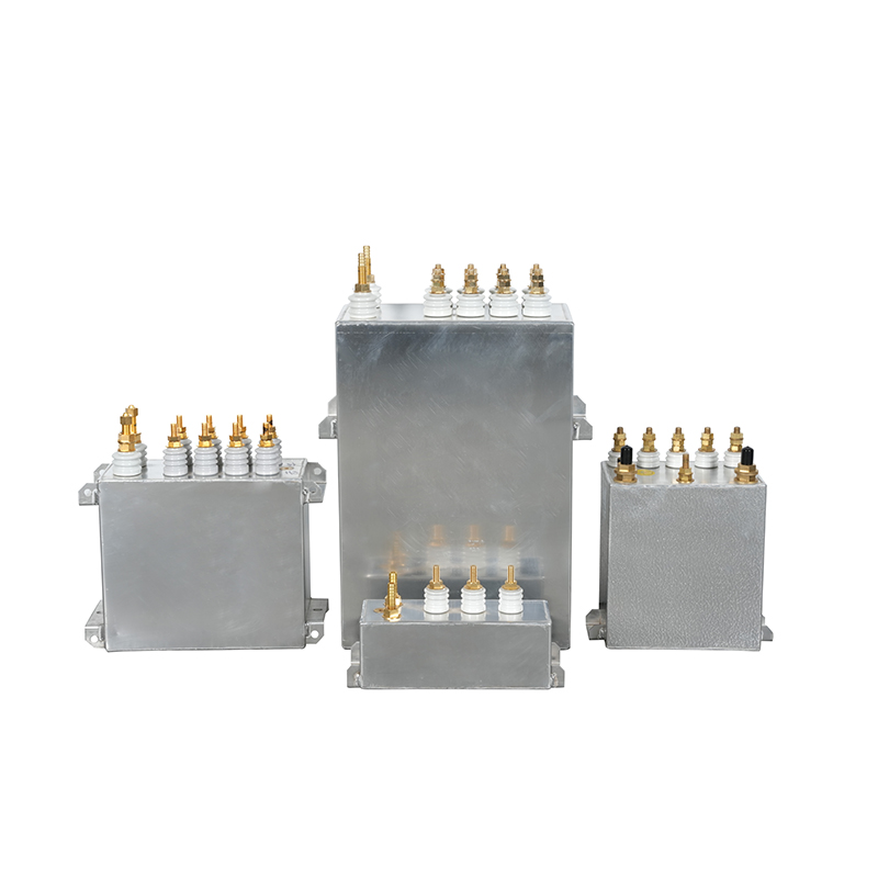
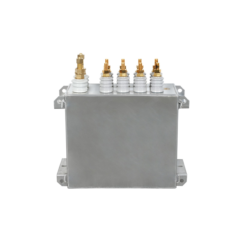 Water-Cooled Induction Heating Capacitor for Continuous Industrial HeatingA water-cooled capacitor series for high-power continuous induction heating, with ratings to 3000 V and construction details relevant to cooling and voltage margin.View Product →
A capacitor rated 3.0 kV will not survive a bus that sits at 3.35 kV for most of the melt. Induction heating capacitors must be selected against measured terminal voltage and measured operating frequency, not against the converter nameplate, because the margin between rating and reality is where repeat failures are born.
| Parameter | Nameplate | Measured in service | Effect on the capacitor |
| Terminal voltage | 3.0 kV | 3.35 kV | Higher dielectric stress, partial discharge starts in voids |
| Operating frequency | 1000 Hz | 650 to 1250 Hz sweep | Dielectric loss and internal heating rise at the top of the band |
| Capacitor current | 1540 A | 2050 A | Fuse and terminal heating, film hotspot above rating |
| Coolant inlet | 35 C | 43 C | Life roughly halved for each 8 C above the rated hotspot |
| Terminal torque | 25 Nm | 12 Nm after cycling | Contact resistance rises, terminals discolour and melt |
Only the nameplate column is a design input. Everything else has to be measured. The frequency sweep deserves particular attention: a bank rated at 1000 Hz but operated across a 500 to 1250 Hz sweep spends part of every cycle above its design loss, and that damage accumulates shift after shift until the unit fails months earlier than its datasheet life suggests.
A capacitor bank carrying 1.3 to 1.5 times its rated current will fail regardless of which film supplier made it. In an induction heating system the capacitor is part of a resonant tank with the coil and the matching transformer, so rectifier harmonics plus any power factor correction on the same bus can shift the resonant point onto a harmonic order and multiply current through the bank.
If measured capacitor current is more than 1.1 times the nameplate value at full power, the fault is in the circuit, not in the capacitor.
The checks are inexpensive. Log capacitor current with a power quality analyser across a complete melt cycle, including the first two minutes when coil impedance is lowest. Compare the peak with the nameplate current, then look for a resonant peak within one or two harmonic orders of the operating frequency. If a detuning reactor or a different capacitance tap is required, that is a circuit change, and it costs far less than a fourth bank.
Terminal heating is the most misdiagnosed failure mode in the bank. A capacitor with a melted terminal block is usually reporting a connection problem, such as an undersized busbar, a loose clamp or an oxidised contact surface, rather than an internal fault in the film.
Torque values are specified cold for a reason. A joint tightened to 25 Nm at installation can relax to 12 Nm after a few hundred melt cycles, which roughly doubles contact resistance and turns the terminal into a heater. Re-torquing at scheduled maintenance is a twenty-minute job that removes one of the most common repeat failures in the plant.
Run these four steps in order, on the failed position, before ordering a replacement. Each step produces a number that can be compared directly with the datasheet, so the decision stops being a guess.
Record terminal voltage, capacitor current, frequency and coolant inlet and outlet temperature across one full melt cycle, including the first two minutes when the cold charge draws the highest current.
Measure flow and inlet temperature at the capacitor rather than at the chiller, check conductivity and hardness, and confirm the unit was vented after the last service.
A power quality analyser over a single cycle shows the current spectrum and any resonant peak close to the operating frequency, which is the fastest way to confirm or rule out overcurrent.
Check torque, discolouration and phase clearance on the busbar and fuses, then compare the failed unit's capacitance with a new one to separate a connection fault from a film fault.
If all four numbers sit inside the datasheet, the remaining possibility is genuine film or process quality, and that is where supplier selection and incoming inspection decide the outcome.
Match the capacitor to the measured duty, not to the furnace nameplate. That means selecting the voltage class one step above the measured terminal voltage, confirming the full frequency band rather than a single frequency, and choosing cooling type from the real ambient and load profile.
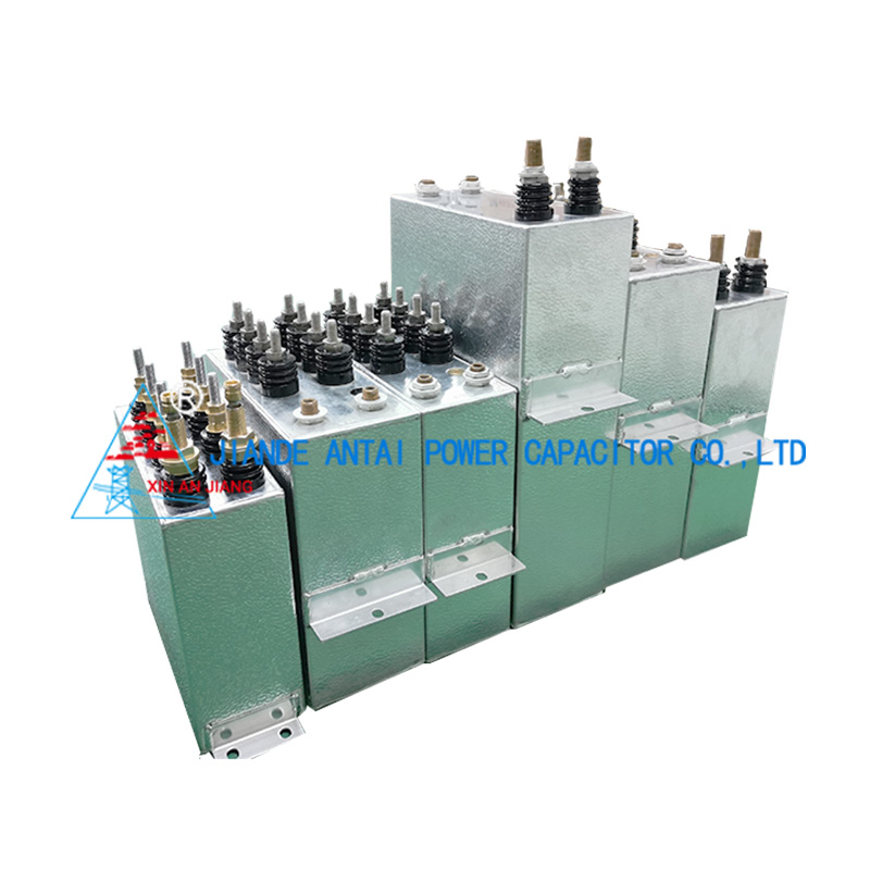
Production control is where those choices become hardware. A manufacturer working with imported raw film, controlled copper tube expansion and withstand-voltage testing on every unit can hold the tolerances the datasheet promises; Jiande Antai Power Capacitor Co., Ltd. has built induction heating and melting capacitors for 40 years in a plant of more than 10,000 square metres, and its manufacturing and testing capability is documented unit by unit.
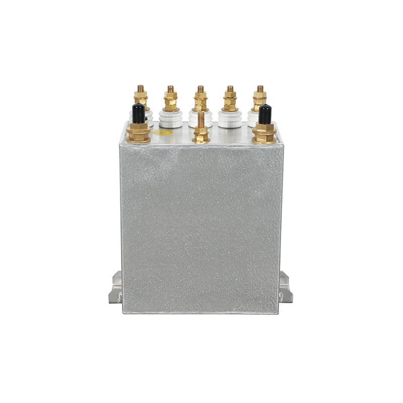
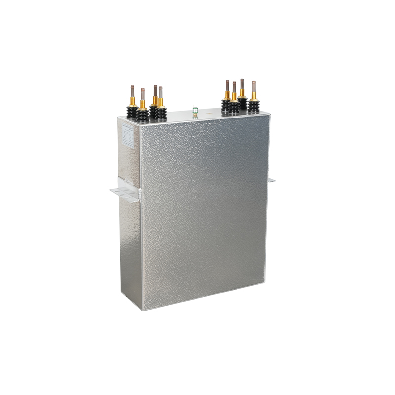 3.6 kV 8000 kvar RFM Medium Frequency Induction Heating CapacitorRFM-series medium-frequency capacitor rated 3600 V and 8000 kvar, with construction and installation details relevant to induction heating system reliability.View Product →
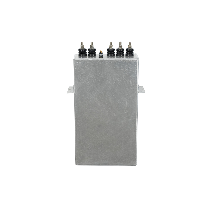
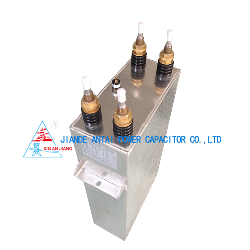 RAM 3300 V 6921 kvar 1200 Hz Induction Heating CapacitorRAM-series medium-frequency capacitor rated 3300 V, 6921 kvar and 1200 Hz, with film dielectric, discharge resistors and installation guidance for industrial heating.View Product →
Under correct conditions a water-cooled induction heating capacitor should give five to eight years of service, or roughly 20,000 to 40,000 operating hours. A failure at six to twelve months is a system signal, not a normal wear-out point, and the four stress factors above should be measured before another unit is installed.
Not directly. Air-cooled units carry less reactive power per unit volume and depend on stable ambient airflow that a melt shop rarely provides. Substituting one into the same footprint usually raises the hotspot temperature and shortens life, even when the electrical ratings appear to match on paper.
Early failures usually trace to a voltage class below the measured terminal voltage, a reversed coolant connection, trapped air in the water circuit, or a terminal that was not re-torqued after installation. Check measured terminal voltage and coolant flow before assuming a product defect.
Use low-conductivity water, typically below 10 microsiemens per centimetre, with low hardness to limit scale inside the copper tubes. Hold the inlet temperature at or below the datasheet value measured at the capacitor inlet, filter the loop, and replace the water on a scheduled basis rather than only when it looks dirty.
Contact Us
News center
information
Tel: +86-571-64742598
Fax: +86-571-64742376
Add: Zhangjia Industrial Park, Genglou Street, Jiande City, Zhejiang Province, China
mobile