 English
 русский
 Deutsch
News
Home / News / Industry News / How Cooling System Design Affects Induction Capacitor Performance & Lifespan
Content
A 3.0 kV, 8400 kvar induction melting capacitor is designed for a dielectric hot-spot ceiling of roughly 85°C. Feed it with cooling water at 38°C instead of the 30°C specified on the datasheet, and the polypropylene film reaches that ceiling after two hours of continuous melting duty. The capacitor does not fail immediately; it ages exponentially faster. Cooling system design is the deciding factor between an induction capacitor that runs for 12 years and one that dies in 22 months.
This article breaks down the specific design and operating decisions — cooling medium, pipe arrangement, flow rate, and inlet temperature — that determine induction capacitor performance and lifespan, and it explains how to verify each one before an overheating failure shuts down your furnace.
Induction capacitors generate heat in three places — the polypropylene dielectric, the metallized electrodes, and the connection terminals — and every 10°C reduction in hot-spot temperature roughly doubles the expected service life.
At 500 to 3000 Hz, the reactive current circulating through the capacitor produces dielectric losses proportional to the dissipation factor (tan delta), plus electrode losses that scale with the square of the current. A 4000 kvar unit at 1000 Hz typically dissipates 8 to 15 kW of heat that must be removed continuously during melting cycles.
A manufacturer cannot eliminate these losses; it can only remove the heat faster and more evenly. The thermal path from the film core to the coolant has four resistances: film-to-case conduction, case-to-coolant convection, coolant flow rate, and inlet coolant temperature. A weakness in any one of them sets the hot-spot temperature that governs the aging rate.
Relative insulation life of polypropylene film versus hot-spot temperature rise.
Polypropylene film capacitors follow an Arrhenius-type aging law: the insulation life halves with each 10°C rise in operating temperature. A capacitor running 20°C above its design hot-spot temperature does not lose 20% of its life; it retains roughly 25% of the life it would have at the rated temperature.
Water-cooled capacitors extract 20 to 50 times more heat per unit surface area than air-cooled designs, which is why virtually all induction melting capacitors above 500 kvar use water cooling.
A water-cooled capacitor routes deionized water through copper tubes embedded in the case or brazed to its exterior. The heat transfer coefficient of forced water flow reaches 500 to 2000 W/m²K, compared with 10 to 100 W/m²K for forced air. This allows a significantly smaller case and a higher reactive power density. An air-cooled unit, in contrast, needs a much larger finned surface and still runs 15 to 25°C hotter at the core.
Manufacturers such as Jiande Antai Power Capacitor Co., Ltd. build their high-power induction series as water-cooled units for this reason; the structural choice is dictated by thermal physics, not by preference.
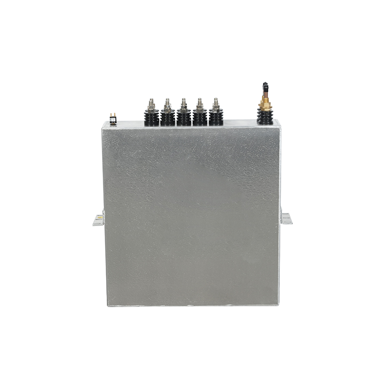
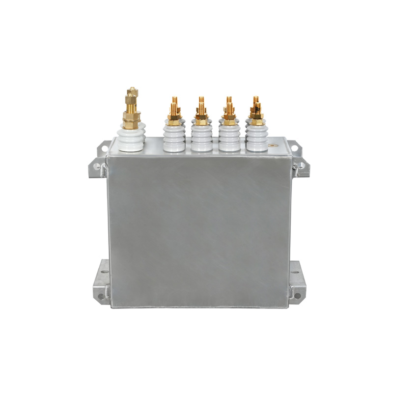 Water-Cooled Induction Heating Capacitor for High-Power SystemsBuilt for long-running induction heating tasks such as metal smelting and forging, this capacitor integrates a precision water-cooling circuit that rapidly dissipates heat under heavy load, ensuring stable operation and extended service life.View Product →
The arrangement of cooling water pipes determines where the coolant flows first, how evenly it splits across capacitor sections, and whether the hottest part of the winding sees the coldest water.
The most common layout in rectangular induction capacitors is a multi-pass serpentine tube. In a series-pass arrangement, the water temperature rises along the path, and the last pass always runs hotter than the first. If the inlet is 30°C and the outlet reaches 36°C, the dielectric in the final pass operates at a measurably higher temperature. In a parallel-pass arrangement, pipe diameter and path length control flow distribution; a 10% difference in path length can create a 15 to 20% flow imbalance and a permanent hot zone in the starved section.
The arrangement of cooling water pipes directly changes heat dissipation effectiveness, and manufacturers validate this geometry during design testing. When you evaluate a replacement capacitor, ask for the thermal test report that documents per-section temperature at rated current and rated flow.
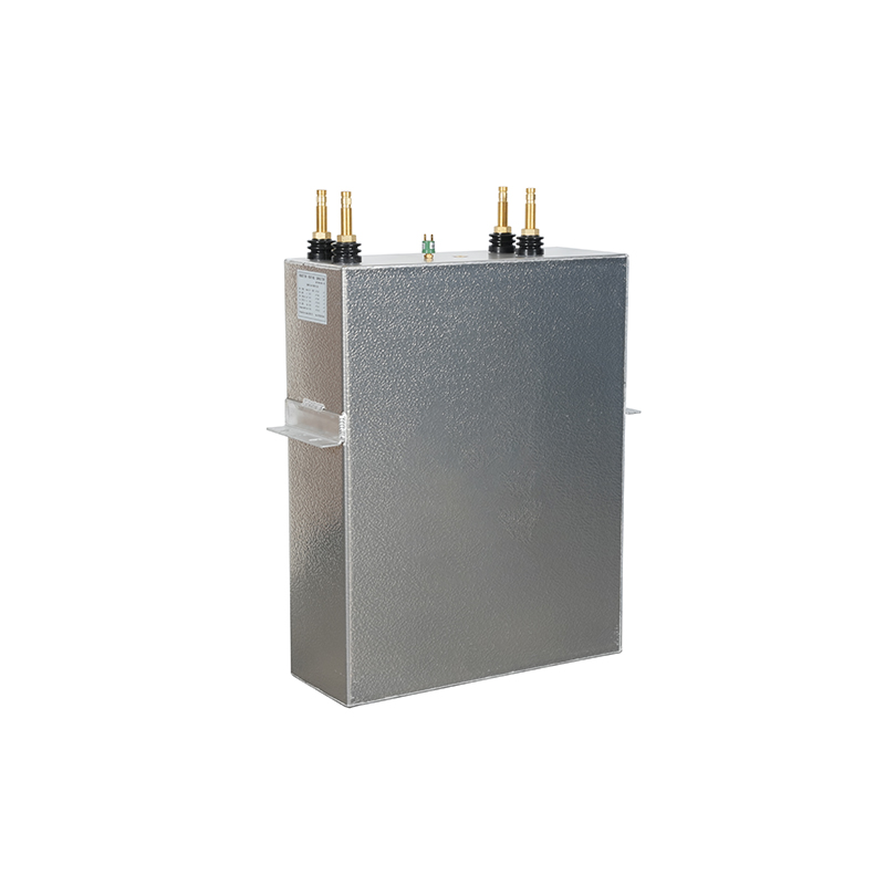
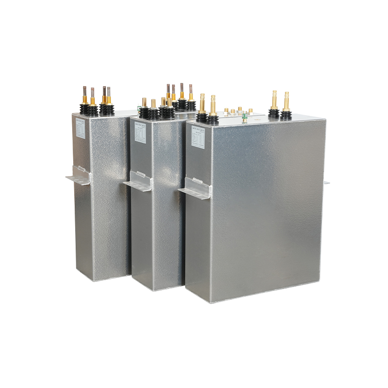 High-Power Water-Cooled Capacitor for Induction FurnacesEngineered with CNC-machined housing and high-purity dielectric materials, this capacitor features integrated temperature and current monitoring plus multiple cooling configurations, making it a reliable replacement that supports stable furnace output and reduced maintenance.View Product →
Three operating parameters decide whether a cooling design actually protects the capacitor: minimum flow rate, maximum inlet temperature, and the measurable pressure drop across the cooling circuit.
These parameters are stated on the capacitor datasheet for a reason. Each one maps directly to a failure mode: low flow produces localized boiling and vapor pockets; high inlet temperature lifts the entire thermal profile; a falling pressure drop indicates a blocked line that will starve the hottest section.
| Parameter | Typical specification | Consequence of violation |
| Inlet water temperature | 30°C maximum (25 to 35°C by rating) | Every 5°C above the limit cuts insulation life by roughly half |
| Flow rate | 4 to 10 L/min per section at 20 to 30°C | Low flow creates hot spots and accelerates dielectric aging |
| Pressure drop | 0.10 to 0.35 MPa across the cooling coil | A drop of more than 15% from baseline signals scale or debris |
| Water conductivity | 10 µS/cm maximum deionized water | Ionized water corrodes copper tubes and lowers insulation resistance |
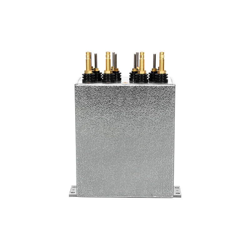
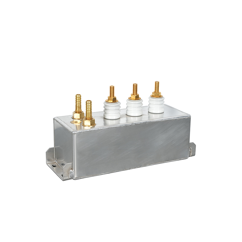 1.5kV 4000kvar 1000Hz Water-Cooled Induction Heating CapacitorRated for 1000Hz operation with 4000kvar compensation, this capacitor uses an efficient water cooling layout to maintain low temperatures during high-load service, offering easy integration into new or existing induction heating systems.View Product →
Most cooling-related capacitor failures are preceded by measurable changes — rising case temperature, higher tan delta, and capacitance drift — that appear weeks before breakdown.
A quarterly thermal and electrical check catches the majority of cooling problems in time. The four checks below do not require opening the capacitor; they use measurements that any maintenance team can take on a running furnace.
For most induction heating and melting capacitors, the maximum inlet water temperature is 30°C, with some high-frequency designs allowing 35°C. Above this limit, the dielectric hot-spot temperature rises proportionally and the insulation life drops by roughly half for every 5°C increase.
Measure the case temperature of each section with an infrared thermometer while the capacitor runs at full rated current. Sections fed by the last cooling pass, or by a parallel branch with higher flow resistance, run 5 to 10°C hotter. A difference above 8°C between sections warrants a cooling circuit inspection.
Only if the furnace duty cycle and reactive power are low enough to keep the core below the same hot-spot ceiling. In practice, air-cooled replacement is rarely viable for melting applications above 500 kvar, because the required fin surface becomes impractically large and the ambient heat load degrades nearby electronics.
Scale from hard water is the most common cause, followed by debris and algae in open-loop systems. Using deionized water with conductivity below 10 µS/cm and flushing the circuit every six months prevents the majority of blockages.
Contact Us
News center
information
Tel: +86-571-64742598
Fax: +86-571-64742376
Add: Zhangjia Industrial Park, Genglou Street, Jiande City, Zhejiang Province, China
mobile