 English
 русский
 Deutsch
News
Home / News / Industry News / The Ultimate Guide to Tank Capacitors: Design, Selection, and Applications
Content
In the world of power electronics and high-frequency systems, certain components are pivotal to achieving efficiency, stability, and reliability. The tank capacitor is one such critical component, serving as the heart of resonant circuits in applications like induction heating and RF power generation. This guide delves deep into the specifics of tank capacitors, offering a professional and detailed resource for engineers, purchasers, and industry professionals. We will explore their function, key selection criteria, and how to maximize their performance and lifespan in demanding operational environments.
A tank capacitor, often paired with an inductor to form an LC "tank" circuit, is designed to store and release electrical energy at a specific resonant frequency. This fundamental operation is crucial for creating efficient oscillatory currents.
Choosing an inappropriate capacitor can lead to premature failure, system inefficiency, and costly downtime. Several technical parameters must be carefully evaluated.
The dielectric material is a primary differentiator in capacitor performance. For high-power, high-frequency applications, the choice is often between film and ceramic capacitors. For instance, polypropylene film capacitors offer superior performance for most induction heating applications compared to ceramic capacitors in terms of power handling and stability. The following table summarizes the key differences relevant to tank circuit use.
| Feature | Film (e.g., Polypropylene) | Ceramic (Class I, e.g., C0G/NP0) |
| Typical Application | High-power induction heating, melting, RF generators | Lower-power RF circuits, high-frequency coupling |
| Capacitance Stability | Excellent; low temperature coefficient | Excellent for Class I; stable |
| Dissipation Factor (DF) | Very low (e.g., 0.0002) | Low (e.g., 0.001) |
| Current Handling | Very High | Moderate to Low |
| Key Advantage | High RMS current, self-healing, reliability in tough conditions | Small size, high-frequency capability, stable |
Beyond selection, proper integration and maintenance are key to longevity. This is where the expertise of a seasoned manufacturer becomes critical.
Following these practices is fundamental to extending the life of a resonant tank capacitor and ensuring system uptime.
The unique properties of tank capacitors make them suitable for several high-power, high-frequency industries.
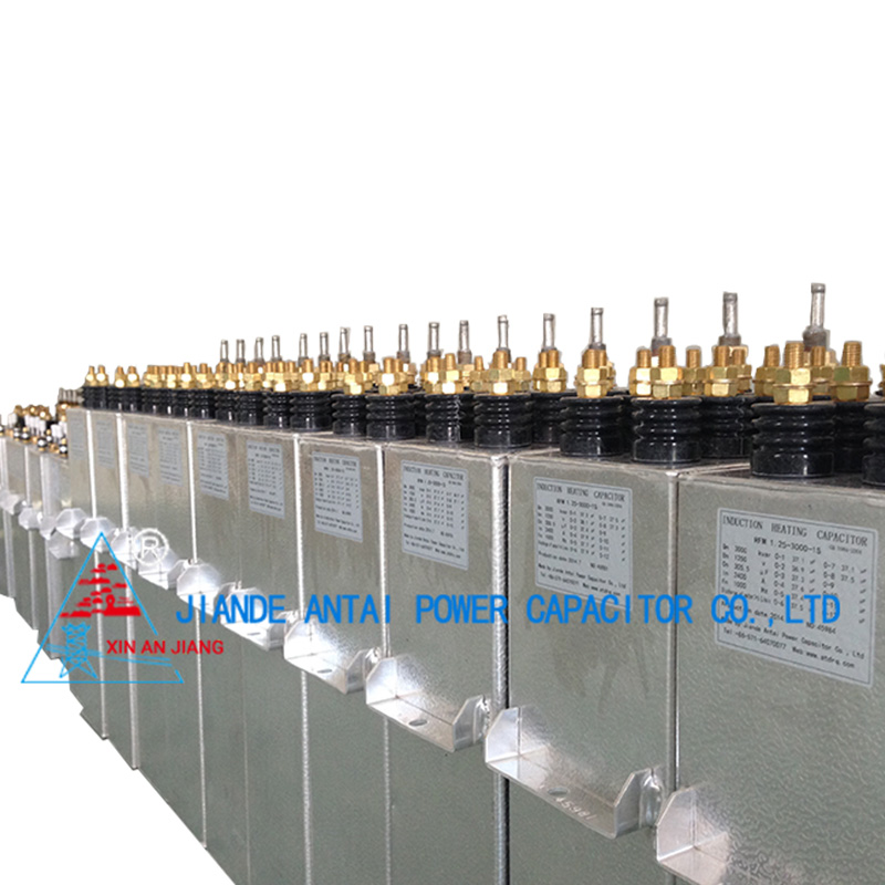
This is the most demanding application. A robust tank capacitor for induction heating furnace must handle extremely high currents and reactive power. They are used in:
- Metal melting furnaces.
- Forging and brazing systems.
- Surface hardening equipment.
In RF plasma generators, broadcast transmitters, and industrial RF heating, tank capacitors help form the resonant network that defines the output frequency and couples power efficiently to the load.
MRI machines and particle accelerators use precise resonant circuits where the stability and low loss of the tank capacitor are paramount for accurate and reliable operation.
Selecting a reliable supplier is as crucial as understanding the technology. Jiande Antai Power Capacitor Co., Ltd. brings four decades of specialized experience to the table. Our 10,000-square-meter factory is equipped with advanced, customized machinery, and we utilize imported raw materials to ensure superior quality from the ground up.
Whether you require a standard high current polypropylene tank capacitor or a custom water cooled tank capacitor design, Antai's commitment to continuous improvement in product quality and service levels ensures we can meet your specific needs and help drive your business success.
The fundamental formula for the resonant frequency (f) of an LC circuit is f = 1 / (2π√(LC)). To calculate tank capacitor value, you rearrange the formula to solve for C: C = 1 / ( (2πf)² L ). You need to know the desired resonant frequency (f) in Hertz and the inductance (L) in Henries. Always consider circuit parasitics and practical tolerances.
The primary failure modes are:
= Overheating due to excessive RMS current or inadequate cooling.
= Dielectric breakdown from overvoltage spikes or transients.
= Degradation of internal connections or metallization from thermal cycling.
= Moisture ingress leading to reduced dielectric strength and increased losses.
Polypropylene film offers an exceptionally low dissipation factor, high dielectric strength, and a stable temperature coefficient. Its "self-healing" property allows it to isolate minor defects, preventing catastrophic failure. These characteristics make it ideal for building a reliable high current polypropylene tank capacitor.
Water cooling becomes necessary when the internal heat generated (I²R losses) cannot be dissipated efficiently through convection or forced air alone. This is typical in very high-power density applications, such as large induction melting furnaces or compact RF generators, where a specially engineered water cooled tank capacitor design is required to maintain safe operating temperatures.
Regular preventive monitoring is key to extending the life of a resonant tank capacitor. Key methods include:
= Measuring and trending the case temperature during operation.
= Using a thermal camera to check for hot spots on connections and the capacitor body.
= Periodically measuring capacitance and dissipation factor (DF) offline to detect degradation.
= Listening for abnormal arcing sounds and monitoring for system performance drift.
[1] B. H. Khan, S. K. Dash, and A. K. Panda, "Thermal Analysis and Design of Water-Cooled Capacitors for High-Frequency Induction Heating," in IEEE Transactions on Power Electronics, vol. 35, no. 8, pp. 7894-7905, Aug. 2020. (This source provides detailed analysis on thermal management challenges and design principles for capacitors in high-power induction systems, supporting the discussion on cooling requirements.)
Contact Us
News center
Jul - 2026 - 01
information
Tel: +86-571-64742598
Fax: +86-571-64742376
Add: Zhangjia Industrial Park, Genglou Street, Jiande City, Zhejiang Province, China
mobile


