Content
In the rapidly evolving landscape of modern power electronics, the stability and efficiency of energy conversion systems hinge on the precise management of electrical signals. At the heart of this management lies the DC Filter Capacitor, a passive yet pivotal component that ensures the smooth operation of circuits ranging from consumer electronics to industrial power drives. As the demand for high-efficiency devices grows, understanding the function and selection of these capacitors becomes essential for engineers and procurement specialists alike. Unlike their AC counterparts, DC capacitors are tasked with the critical role of filtering, smoothing, and energy storage in direct current applications. They act as the reservoir that absorbs voltage ripples and suppresses electrical noise, thereby protecting sensitive components and ensuring a reliable power supply. Whether in electric vehicles, renewable energy inverters, or sophisticated industrial machinery, the DC Filter Capacitor is fundamental to achieving optimal performance and longevity in electronic systems.
Power electronics are fundamentally concerned with the conversion and control of electric power using electronic switches. In these systems, the conversion process—typically from AC to DC or DC to DC—rarely results in a perfectly smooth output. Instead, the output often contains residual AC components known as ripples, alongside high-frequency noise generated by the switching action of transistors like IGBTs and MOSFETs. This is where the DC link capacitor becomes indispensable. Positioned at the intermediate stage of converters, often referred to as the DC link, this capacitor serves as a stabilizing energy buffer. It smooths out the pulsating DC voltage, ensuring that the downstream inverter or load receives a steady and clean voltage supply. Without this critical filtering, the voltage ripple could cause malfunctions, overheating, or electromagnetic interference (EMI) that disrupts the entire system's operation.
The specific role of a DC link capacitor is defined by its placement within the circuit architecture. In a typical variable frequency drive (VFD) or inverter, the AC input is first rectified to DC. This DC is not perfectly smooth; it often resembles a bumpy line corresponding to the peaks of the AC waveform. The DC link capacitor charges up during the voltage peaks and discharges during the drops, effectively filling in the valleys to create a flat DC line. This function is critical for the inverter stage, which relies on a stable DC voltage to synthesize a clean AC output for motors. Furthermore, the DC link capacitor must handle significant ripple currents, making its Equivalent Series Resistance (ESR) a key parameter in design considerations.
| Parameter | Role in DC Link |
| Capacitance | Determines the amount of ripple voltage reduction. |
| Voltage Rating | Must exceed the peak DC bus voltage to prevent breakdown. |
| Ripple Current | Must handle the AC current flowing through the capacitor without overheating. |
While the terms "link" and "bus" are often used interchangeably, the DC bus filter capacitor emphasizes the component's role in filtering the entire bus structure. In high-power applications, the bus bars carry large currents, and the inductance of these bars can interact with switching currents to create voltage spikes. The DC bus filter capacitor is placed physically close to the switching modules to provide a low-impedance path for high-frequency noise. By shunting this noise to ground, it prevents voltage overshoots that could destroy the switching semiconductors. This mechanism is vital for the electromagnetic compatibility (EMC) of the system, ensuring that the device does not emit excessive noise that could interfere with other electronic equipment.
Selecting the right capacitor for a DC filter application involves navigating a trade-off between size, cost, and performance. However, two parameters stand out as non-negotiable for high-efficiency designs: Equivalent Series Resistance (ESR) and ripple current rating. In switching power supplies, the capacitor is subjected to high-frequency AC currents superimposed on the DC voltage. This ripple current causes internal heating within the capacitor due to the ESR. Excessive heat is the primary enemy of capacitor longevity, leading to electrolyte evaporation and eventual failure. Therefore, a low ESR DC capacitor is critical for minimizing heat generation and maximizing operational life. Engineers must meticulously calculate the ripple current requirements of the circuit and select a capacitor that not only meets the capacitance value but also boasts a ripple current rating that exceeds the application's demands with a comfortable safety margin.
The term low ESR DC capacitor refers to a component engineered to have minimal internal resistance. This characteristic is paramount in high-frequency switching applications. When a capacitor with high ESR is subjected to ripple current, the voltage drop across the resistance ($V = I \times R$) can be significant, effectively modulating the DC voltage and negating the filtering effect. Moreover, the power dissipated as heat ($P = I^2 \times R$) can rapidly degrade the internal materials. Utilizing a low ESR DC capacitor ensures that the capacitor maintains its filtering efficiency across the frequency spectrum, from the fundamental switching frequency up to the high-order harmonics. This is particularly important in applications like electric vehicle chargers and server power supplies where efficiency and thermal management are critical constraints.
| Capacitor Type | Typical ESR | Best For |
| Standard Electrolytic | High | Low-frequency filtering (50/60Hz smoothing) |
| Low ESR Electrolytic | Medium | Switching power supplies, DC links |
| Ceramic / Film | Very Low | High-frequency decoupling, snubbers |
Effective ripple current management is a multi-faceted engineering challenge. The DC Filter Capacitor must be capable of handling the RMS (Root Mean Square) value of the ripple current without exceeding its thermal limits. This often involves using large-can capacitors with screw terminals to handle currents exceeding 100A in industrial drives. The low ESR DC capacitor is the preferred solution here because it allows for higher current handling without thermal runaway. Additionally, designers often parallel multiple smaller capacitors to share the current load and reduce the overall equivalent ESR. This strategy also reduces the equivalent series inductance (ESL), which is beneficial for filtering very high-frequency noise.
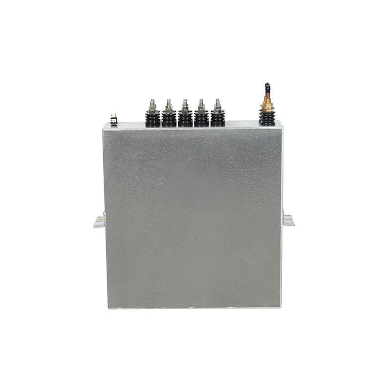
Among the various types of capacitors available, the aluminum electrolytic DC capacitor reigns supreme in high-voltage, high-capacitance applications. This dominance is due to the unique physical properties of aluminum electrolytics, which offer the highest volumetric efficiency—meaning they provide the most capacitance per unit volume. Constructed using an etched aluminum anode and a liquid electrolyte, these capacitors achieve high capacitance values (often thousands of microfarads) in a relatively compact package. This makes them the ideal choice for DC link capacitor applications where space is constrained but energy storage needs are high. Modern manufacturing advancements have significantly enhanced their performance, improving their ripple current capability and extending their service life even under harsh operating conditions.
The construction of an aluminum electrolytic DC capacitor involves sophisticated chemical processes. The aluminum foil is etched to increase its surface area massively, which directly correlates to capacitance. This etching process allows for a "spongy" layer that holds the electrolyte, the conductive medium. One of the primary advantages of this technology is the self-healing property of the oxide layer. If a localized breakdown occurs in the dielectric oxide layer, the resulting heat can clear the fault, restoring the insulation. This makes the aluminum electrolytic DC capacitor remarkably robust for DC filter applications where voltage surges are not uncommon.
| Feature | Benefit |
| Etched Foil | Maximizes surface area for high capacitance. |
| Liquid Electrolyte | Ensures good contact with the anode for high conductivity. |
| Sealed Case | Prevents drying out and maintains internal pressure. |
The life expectancy of an aluminum electrolytic DC capacitor is intrinsically linked to temperature. As a general rule of thumb, the life of an electrolytic capacitor halves for every 10°C increase in operating temperature (Arrhenius law). Therefore, selecting a capacitor with a high-temperature rating (e.g., 105°C or 125°C) is crucial for reliability, even if the ambient temperature is lower. This provides a safety margin against the internal heating caused by ripple current. When comparing these to other types like film capacitors, electrolytics generally have a shorter lifespan, but their cost and size advantages make them the industry standard for DC link capacitor banks in inverters and drives. Engineers must calculate the "hot spot" temperature to ensure the chosen capacitor will meet the product's warranty and reliability goals.
The utility of DC Filter Capacitor technology permeates nearly every sector of the electronics industry. Any application that converts power—whether from the grid to a DC microgrid, or from a battery to a motor—relies on these components to ensure stability. In the burgeoning field of renewable energy, the intermittent nature of solar and wind power requires robust filtering to stabilize the DC voltage before it is inverted to AC for the grid. Similarly, in the automotive industry, the shift towards electric vehicles has created a massive demand for capacitors capable of handling high-voltage DC buses and the high ripple currents generated by regenerative braking systems. The aluminum electrolytic DC capacitor is ubiquitous in these settings, providing the necessary bulk capacitance in a rugged form factor.
In solar photovoltaic (PV) systems, the energy generated by panels is DC, which must be converted to AC for grid connection. The inverter stage relies heavily on the DC bus filter capacitor to smooth the variable DC input from the panels. The fluctuating nature of sunlight means the input voltage varies constantly; the capacitor buffers these changes to provide a stable input for the inversion stage. Furthermore, the high switching frequencies of modern inverters generate significant high-frequency noise that the DC Filter Capacitor must shunt away to prevent interference with the grid's synchronization signals. The reliability of these capacitors is critical, as maintenance in remote solar farms can be costly and difficult.
Industrial motor drives are perhaps the most demanding environment for a low ESR DC capacitor. These drives control large motors used in pumps, fans, and conveyors. The rectifier stage converts the incoming AC to DC, but the rapid switching of the IGBTs in the inverter stage draws pulsed currents from the DC bus. The DC link capacitor must supply these high instantaneous currents. If the capacitor's ESR is too high, voltage dips occur on the DC bus, which can cause the drive to trip or malfunction. Additionally, the capacitors in these environments often face high ambient temperatures, necessitating robust aluminum electrolytic DC capacitor designs with high ripple current ratings and long life expectations to minimize downtime.
The most common reason for failure in a DC Filter Capacitor, particularly in aluminum electrolytic DC capacitor types, is the evaporation of the electrolyte due to excessive heat. This heat is generated by the ripple current flowing through the capacitor's internal Equivalent Series Resistance (ESR). Over time, as the electrolyte dries out, the capacitance decreases and the ESR increases, leading to a cascade effect that ultimately causes the capacitor to overheat and potentially bulge or rupture. Voltage surges that exceed the component's rated voltage can also puncture the dielectric oxide layer, causing catastrophic short circuits.
While the terms are often used synonymously, there is a subtle distinction in functional emphasis. A DC link capacitor specifically refers to the capacitor placed in the intermediate DC link of a converter, acting primarily as an energy reservoir to bridge the gap between the rectifier and inverter stages. A DC filter capacitor is a broader term that encompasses any capacitor used to filter noise or ripple from a DC line. In many circuits, the same component serves both functions, but "link" emphasizes energy storage, while "filter" emphasizes noise suppression.
Using a standard capacitor in a place designed for a low ESR DC capacitor is generally not recommended. Standard capacitors have higher internal resistance, which means they will generate significantly more heat when subjected to the high ripple currents typical of switching power supplies. This excess heat will drastically reduce the lifespan of the capacitor and could cause it to fail prematurely. Furthermore, the higher ESR will result in larger voltage ripples on the DC bus, potentially leading to instability in the load circuit.
Choosing the right capacitance value depends on the acceptable ripple voltage and the load current. A larger capacitor will result in lower ripple voltage but will be physically larger and more expensive. Engineers use the formula $C = I / (f \times V_{ripple})$ to estimate the required capacitance ($C$) based on load current ($I$), switching frequency ($f$), and allowable ripple voltage ($V_{ripple}$). However, other factors such as ESR, voltage rating, and temperature must also be considered when selecting the specific DC Filter Capacitor for a reliable design.
Contact Us
News center
Jul - 2026 - 27
information
Tel: +86-571-64742598
Fax: +86-571-64742376
Add: Zhangjia Industrial Park, Genglou Street, Jiande City, Zhejiang Province, China
mobile
 English
 русский
 Deutsch


