 English
 русский
 Deutsch
News
Home / News / Industry News / W How to Choose Capacitors for Induction Hardening and Heat Treatment Equipment
Content
A 300 kW hardening converter running at 1,000 Hz pushes 600 to 900 kvar of circulating reactive power through its tank capacitor at full load. Order a 400 kvar bank because the nameplate says 300 kW, and the dielectric runs hot from the first shift.
That mismatch sits behind most premature capacitor failures on induction hardening, forging, and heat treatment lines. Choosing capacitors for induction hardening and heat treatment equipment is a frequency and current problem first, and a power problem second. Four nameplate values have to be fixed in order: rated frequency, rated voltage, reactive power in kvar, and cooling method. Case dimensions, terminal layout, and water connection orientation all follow from those four.
The sequence below is the one used to match replacement capacitors to running lines between 50 Hz and 10 kHz, and to specify new banks for parallel resonant inverters.
The rated frequency on a capacitor nameplate is a hard limit. Usable reactive power falls as frequency rises, so a bank rated 4,000 kvar at 1,000 Hz cannot deliver 4,000 kvar at 3,000 Hz.
Dielectric loss scales with frequency, capacitance, voltage squared, and the loss tangent of the film. At 1,000 Hz a well-made all-film polypropylene unit stays cool at rated kvar. At 3,000 Hz the same unit generates roughly three times the internal heat for the same reactive output, and the thermal margin disappears. That is why induction heating capacitors carry a specific frequency rating, and why a 1,000 Hz part should never be swapped into a 3,000 Hz position.
| Process | Frequency band | Capacitor voltage class | Cooling |
| Induction melting, ferrous | 50-500 Hz | 1.5-3.0 kV | Water |
| Billet heating and forging | 500-1,000 Hz | 2.0-3.0 kV | Water |
| Surface hardening | 1,000-10,000 Hz | 2.0-3.6 kV | Water or air |
| Tempering and stress relief | 50-1,000 Hz | 1.0-2.0 kV | Air or water |
Pick a capacitor rated at or above the highest frequency the inverter can produce, and confirm the kvar figure is quoted at that frequency rather than at 50 Hz. This guide to selecting medium frequency induction heating capacitors covers the same trade-offs from a throughput angle.
Capacitor kvar is set by the circulating reactive power in the resonant tank, not by the converter rating. Plan on 3 to 4 times the converter output for melting duty and 1.5 to 2.5 times for surface hardening.
A parallel resonant tank stores far more reactive power than the inverter delivers to the workpiece. The ratio is the loaded quality factor of the tank, typically 8 to 15 for a tightly coupled hardening coil and 5 to 8 for a large melting coil with a loose charge. The calculation is short: measure coil inductance L, choose the resonant frequency f, and solve C = 1 / (4 pi squared f squared L). At resonance, reactive power follows from Q = 2 pi f C V squared. Add 15 to 20 percent headroom, because capacitance drifts with temperature and a partly filled furnace changes the load.
Practical midpoints. Exact values depend on coil coupling, tank Q, and charge geometry.
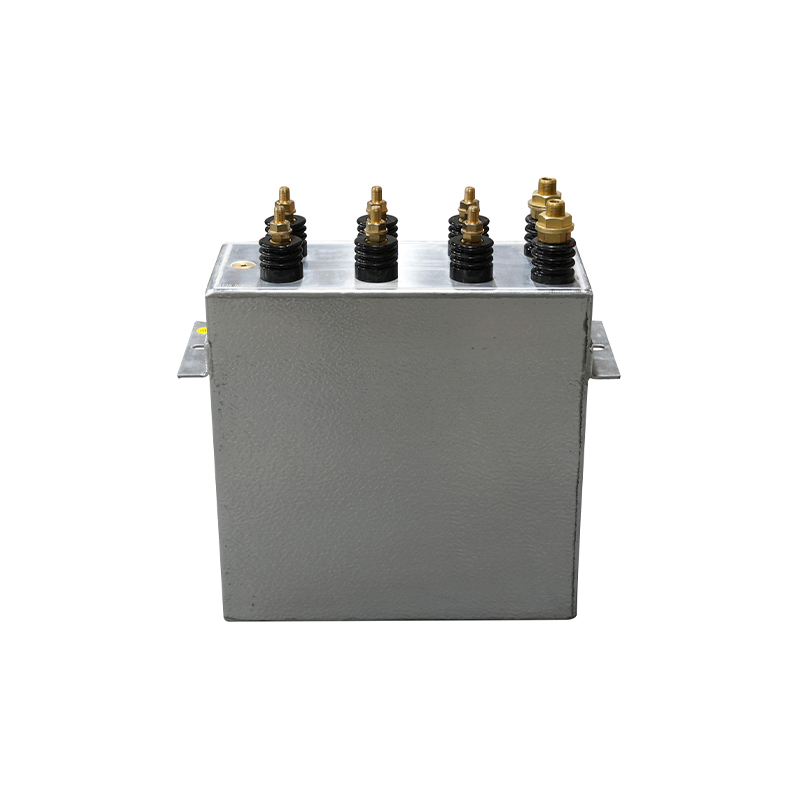
Here is how the numbers scale in practice: a 3.0 kV, 8,400 kvar, 700 Hz unit serves a large melting installation, not a 300 kW hardening cell.
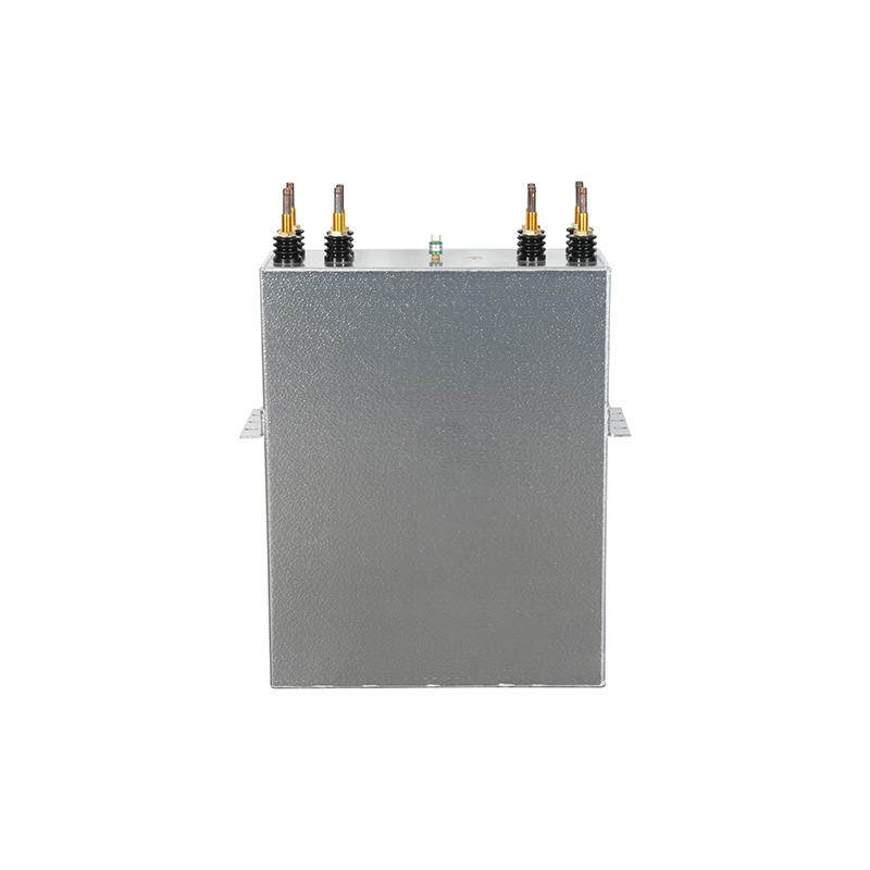 3.0 kV 8,400 kvar RAM Melting CapacitorRAM capacitor rated 3.0 kV, 8,400 kvar at 700 Hz for large melting installations; rated voltage must cover the highest RMS tank voltage.View Product →
Rated voltage has to cover the highest RMS tank voltage the line can reach, not the value measured at the normal working point.
Tank voltage rises when the load leaves the coil. In a parallel resonant circuit, damping falls and circulating voltage can climb 15 to 30 percent above the full-load figure within milliseconds. A 3.0 kV capacitor on a tank that reaches 3.4 kV at no load is not derated, it is over-stressed, and partial discharge starts eating the film immediately.
Log the tank RMS voltage at full load, at no load, and at the worst coupling condition the process will ever see. Take the highest value, add 10 to 15 percent, then step up to the next standard voltage class. Standards such as IEC 60110-1 and GB/T 3984 define permitted overvoltages for induction heating capacitors, so read the datasheet instead of assuming a universal 1.1 times rated voltage allowance.
Water cooling is the default above roughly 500 kvar per unit or on lines that run continuously. Air cooling wins on intermittent duty, in clean bays, and where a cooling loop is impractical.
Water-cooled units concentrate heat removal inside the case, and the routing of cooling tubes affects how evenly that heat leaves the winding. Follow the manufacturer's inlet and outlet orientation instead of re-plumbing a unit to fit an existing manifold. A 4.0 kV, 600 Hz furnace capacitor is a typical continuous-duty choice:
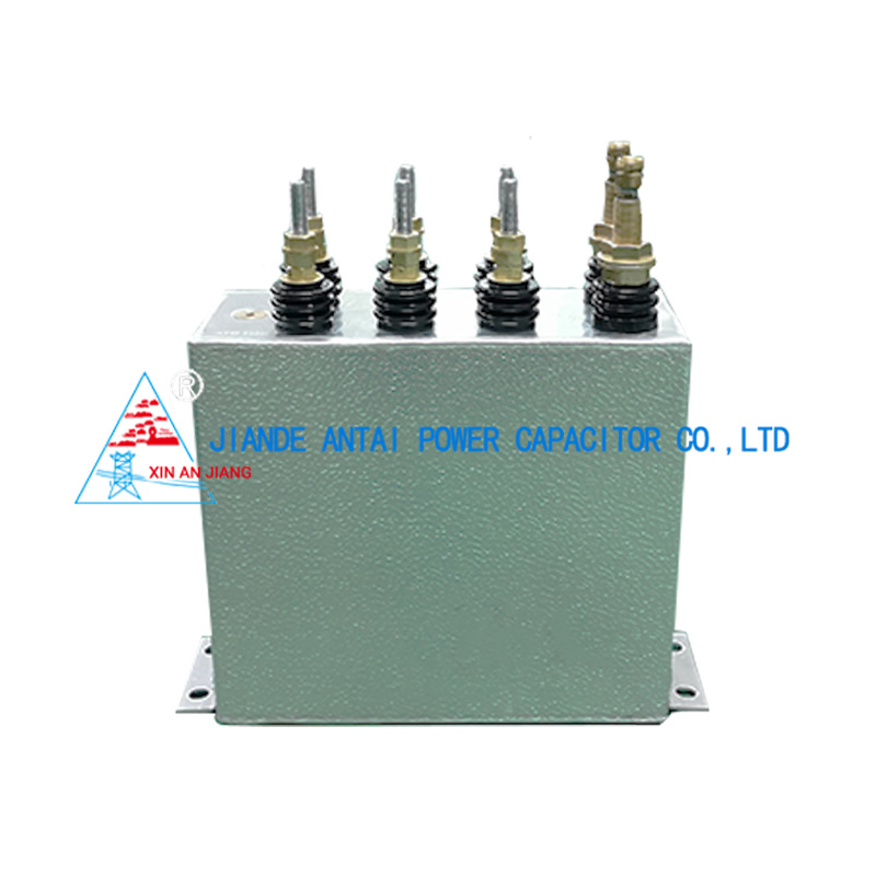
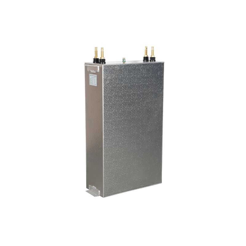 4.0 kV 600 Hz Water-Cooled Furnace CapacitorContinuous-duty water-cooled capacitor for high-frequency induction furnaces, rated 4.0 kV at 600 Hz, with self-healing film dielectric and internal discharge resistors.View Product →
Air-cooled units need derating above 40 C ambient, unobstructed convection paths, and periodic cleaning. Dust-loaded foundry air clogs fins and quietly removes the thermal margin the nameplate assumes.
Two capacitors with identical nameplate ratings can differ by a decade in service life, and the difference usually sits in the film, the impregnation process, and whether the unit was aged before shipment.
All-film polypropylene with metallized electrodes and a thickened edge gives self-healing behaviour at the current densities seen in hardening tanks. Vacuum impregnation removes air and moisture from the winding; residual voids lower the partial discharge inception voltage, and partial discharge is what eventually perforates the film. Controlled aging under elevated voltage and temperature stabilizes capacitance and screens out weak units before they ship.
Ask for measured values per unit rather than a compliance statement: capacitance within plus or minus 5 percent of nominal, loss tangent between 0.0002 and 0.0005 at rated frequency for all-film polypropylene, and a partial discharge or withstand voltage result tied to each serial number.
Run these five steps in order for every new bank and every replacement order.
For intermittent tempering and stress relief lines running a few hours a day in a clean bay, an air-cooled unit is often the better match:
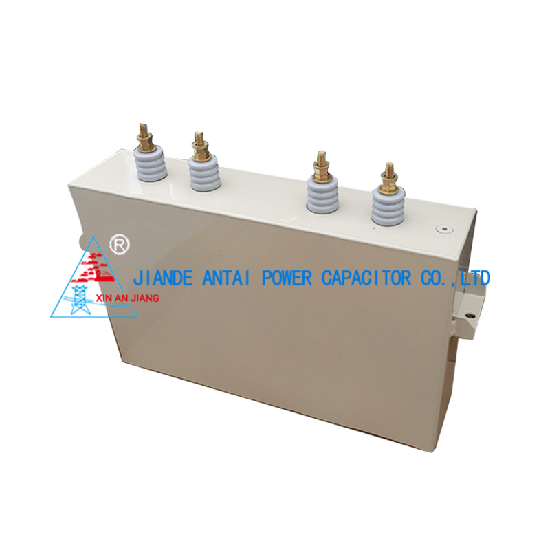
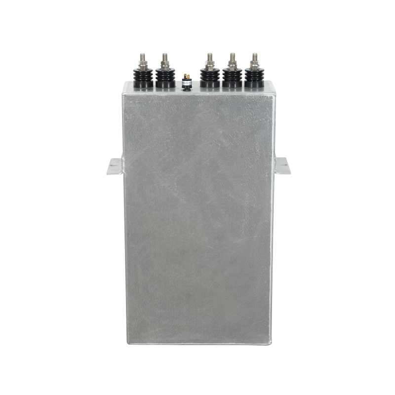 Air-Cooled Induction Heating Capacitor for Intermittent LinesAir-cooled capacitor for 50/60 Hz induction heating and tuning circuits, up to 800 V and 1000 kvar, suited to intermittent tempering in clean bays.View Product →
Confirm six items in writing before the purchase order goes out, because each one has stopped a line somewhere.
Manufacturing depth matters here. A supplier that winds, impregnates, ages, and pressure-tests in its own plant can hand over per-unit data and hold tolerances across a repeat order; an assembly-only supplier usually cannot. The factory and quality control setup behind the capacitors is worth reviewing before a first order, especially for melting banks where one failed unit idles a furnace.
Specify a capacitor rated at 1,000 Hz or higher, and check that the kvar figure is quoted at that frequency. A 1,200 Hz or 1,500 Hz unit leaves useful margin if the inverter is later pushed to its upper frequency limit.
For melting duty, plan on roughly 1,500 to 2,000 kvar for a 500 kW converter, then verify against coil inductance and the frequency the furnace actually runs at. The exact figure moves with charge size and scrap quality.
No. Water-cooled induction heating capacitors are designed around a specified flow rate and an inlet temperature of 35 C or lower. Running one dry or with restricted flow raises the internal hot spot past the film limit within minutes.
Replace on measurement, not on a calendar. Track capacitance and loss tangent every six to twelve months. Drift beyond plus or minus 5 percent, a doubled loss tangent, coolant leakage, or terminal discoloration means the unit should come out of service.
Contact Us
News center
information
Tel: +86-571-64742598
Fax: +86-571-64742376
Add: Zhangjia Industrial Park, Genglou Street, Jiande City, Zhejiang Province, China
mobile