 English
 русский
 Deutsch

News
Home / News / Industry News / How to Choose Between High Voltage Shunt and DC Link Capacitors for Power Systems
Content
When you are choosing between high voltage shunt capacitors and DC link capacitors for power systems, let the circuit topology make the decision for you. Shunt capacitors belong on the AC side of the network to correct power factor and support voltage. DC link capacitors belong on the DC bus of a converter to stabilize voltage and absorb ripple current. These are different jobs, and mixing them up is the most expensive mistake you can make.
This guide gives you a direct selection framework built from practical engineering data. You will learn the defining characteristics of each capacitor type, the four-step decision process that prevents specification errors, and real-world examples from industrial power and induction heating systems.
Selection Rule
If the capacitor sees line frequency and supplies reactive power, it is a shunt capacitor. If the capacitor sees switching frequency and controls ripple on a DC bus, it is a DC link capacitor.
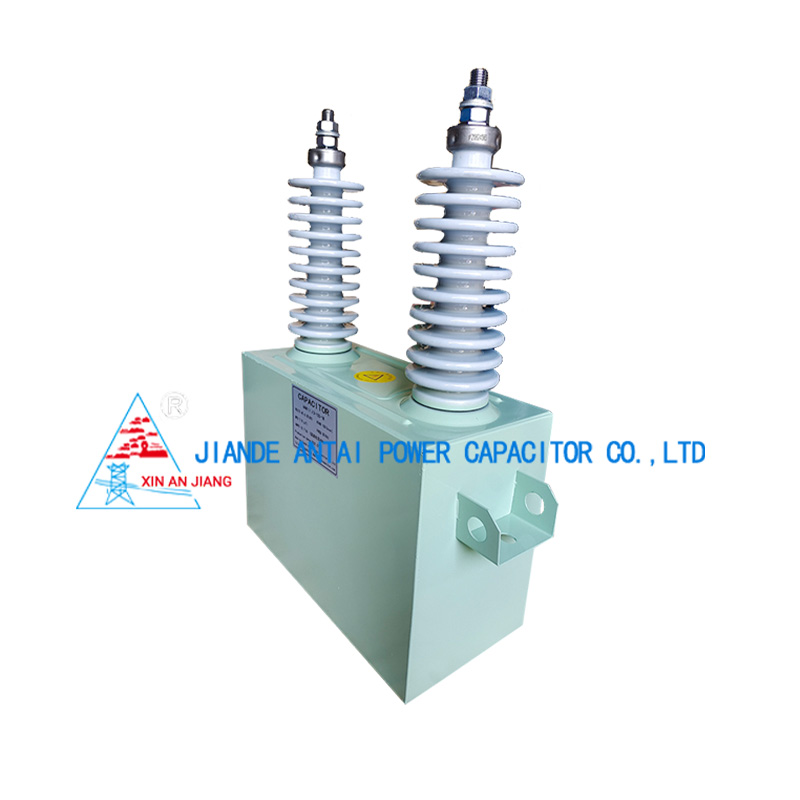
High voltage shunt capacitors connect in parallel to the AC power network at the medium voltage bus. They supply capacitive reactive power to correct the power factor of inductive loads and to stabilize the bus voltage during load changes. Their operation is defined by line frequency, not switching frequency.
The reactive power output of a shunt capacitor is V squared times angular frequency times capacitance. At 10kV and 50Hz, a 1MVAr shunt capacitor bank draws roughly 100A of charging current. In an industrial melting facility, a shunt bank of 3MVAr to 10MVAr reduces line current by 15 percent to 25 percent and lowers transformer losses.
For a deeper look at how these components stabilize the grid, see our article on HV shunt capacitor grid stabilization.
Core Definition
A high voltage shunt capacitor is a reactive power compensation device connected in parallel to an AC network, designed to deliver capacitive reactive power at the line frequency of the system.
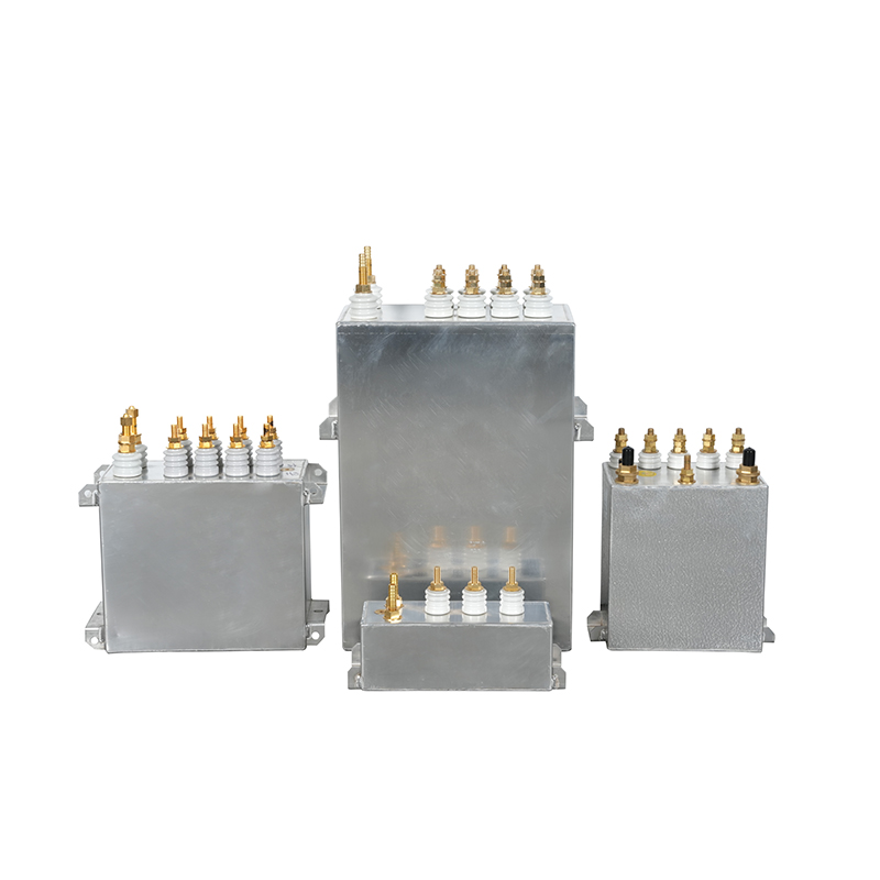
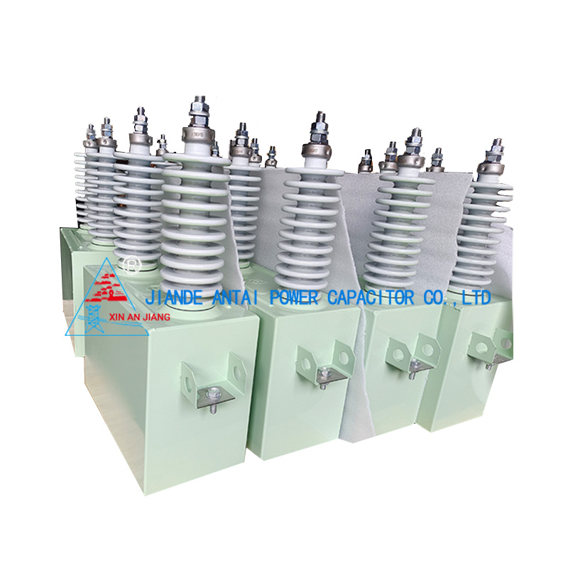 Single-Phase High-Voltage Film Capacitor for Power Factor CorrectionThis capacitor uses polypropylene film and insulating oil to improve power factor, reduce line losses, and support voltage in AC power systems, making it a key component for reactive power compensation.View Product →
DC link capacitors sit directly across the DC bus of a power converter. They smooth the rectified voltage waveform, absorb ripple current from the inverter stage, and hold the bus voltage within acceptable limits during load transitions. Their entire design life is governed by the spectral content of the current they carry.
In a 700V DC bus of an active front end converter, a DC link film capacitor is sized between 1000uF and 5000uF, and rated to carry ripple current of 20A to 80A at 10kHz switching. The equivalent series resistance of the capacitor converts that current into heat. Every 10 degrees C of core temperature reduction doubles the expected service life.
To understand how these components support power electronic systems, read our technical article on the DC filter capacitor in power electronics.
Core Definition
A DC link capacitor is a film capacitor connected across the DC bus of a power converter, sized to absorb ripple current and maintain bus voltage stability under switching frequency current stress.
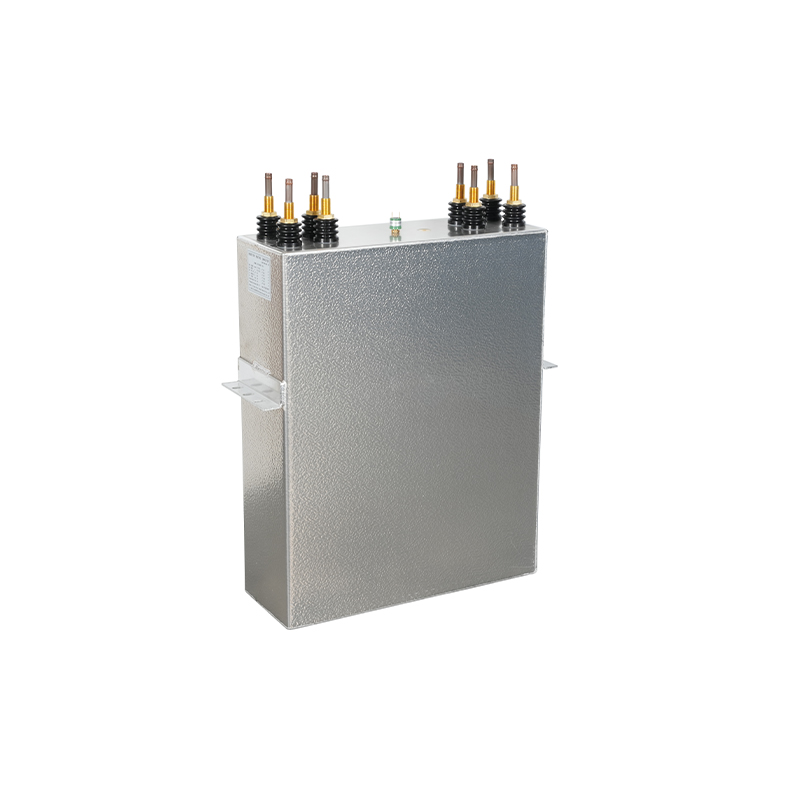
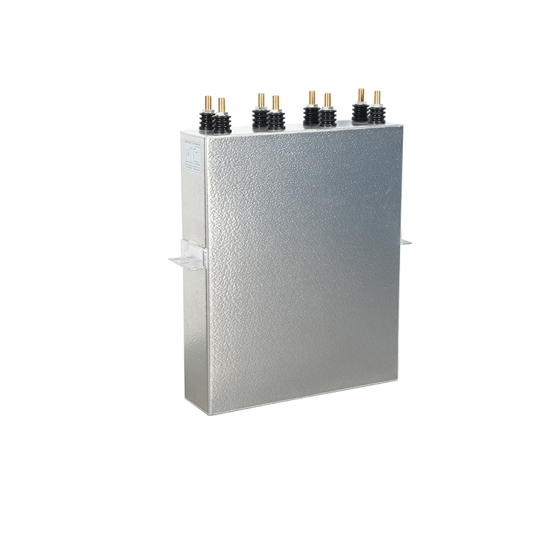 High-Voltage DC Filter Capacitor for Ripple SuppressionDesigned for high-voltage DC supplies, this capacitor filters high-frequency noise and harmonics, enhancing power quality and stability in inverters, UPS, and charging systems.View Product →
The decision between high voltage shunt capacitors and DC link capacitors is, in most systems, determined by where you place the capacitor and what frequency it must handle. But the sizing process follows four distinct steps that apply to either type.
Data from field returns shows that 70 percent of premature capacitor failures in industrial power systems trace back to step one or step two being skipped. When a capacitor from the wrong family is used, it does not fail slowly. It fails catastrophically.
Logarithmic scale: DC link capacitors operate at 100x to 500x the voltage frequency of shunt capacitors.
Field Data Point
Thermal stress from ripple current is consistently the leading cause of end-of-life in DC link capacitor applications.
The table below summarizes the critical specification differences that drive the selection decision.
| Attribute | HV Shunt Capacitor | DC Link Capacitor |
| Circuit position | AC bus, parallel to load | DC bus, parallel to converter |
| Voltage waveform | Sinusoidal AC | Pulsed DC with ripple |
| Dominant frequency | 50Hz / 60Hz | 5kHz to 30kHz |
| Primary rating | kVAr reactive power | Ripple current and capacitance |
| Capacitance range | 20uF to 500uF | 500uF to 5000uF |
| Key failure mode | Dielectric breakdown from overvoltage | Thermal runaway from ripple current |
| Cooling requirement | Air natural | Air forced or water |
| Typical standard | IEC 60871 | IEC 61071 |
Every row in this table is a guardrail. If your capacitor spec sheet does not match the row for the intended position, the component is the wrong one.
Key Insight
The frequency column is the first one to check. If you select a capacitor for 60Hz but the current spectrum is actually 10kHz, the component will fail thermally long before its rated voltage is reached.
An induction melting furnace is a real-world case where both capacitor types appear in the same installation. The medium voltage supply to the melting furnace requires a high voltage shunt capacitor bank to correct the power factor of the furnace transformer and the harmonic filter network. At the same time, the solid state medium frequency power supply drives the furnace coil with a DC link capacitor on the rectifier bus to absorb the ripple current from the inverter stage.
In this scenario, an AC side shunt bank rated 6.6kV and 2.4MVAr handles the reactive power demand of the plant. The furnace converter DC bus, typically rated 1200V to 1500V, uses DC link film capacitors of 3000uF to 5000uF with water cooling at the high end. Our RAM series 3.0kV 8400kVar element is a specifically engineered capacitor for this class of furnace duty.
Shunt bank corrects power factor and supports grid voltage.
DC link bank controls ripple and holds the converter bus stable.
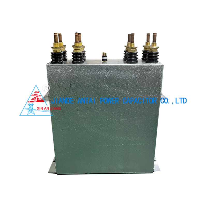
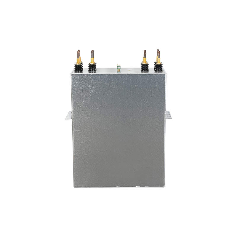 3.0kV 8400kvar Induction Heating and Melting CapacitorWith 3.0kV and 8400kvar at 700Hz, this capacitor enables rapid, precise heating and melting of metals, featuring closed-loop temperature control for uniform results in casting and heat treatment.View Product →
Why It Matters
In a single furnace installation, the shunt bank and the DC link bank work independently, but a failure in either one takes the whole furnace offline.
Three recurring specification errors drive more than half of the premature capacitor failures reported in industrial power electronics.
In cost terms, the direct replacement cost of a failed HV shunt capacitor is typically 2 percent to 4 percent of the total installation cost. But the system downtime that follows can cost 10 times the capacitor price in lost production.
Procurement Warning
When you compare offerings from different capacitor manufacturers, the thermal rating is the first specification to verify. A capacitor that looks cheap on paper often becomes expensive after the first unscheduled shutdown.
No. A high voltage shunt capacitor is designed for sinusoidal line frequency voltage. A DC link application exposes it to continuous switching frequency ripple current that the internal elements cannot dissipate, which causes thermal failure.
Use the energy balance equation: C equals P divided by two times f_sw times delta V squared. Where P is the power level, f_sw is the switching frequency, and delta V is the allowed voltage ripple. The result gives the minimum capacitance needed to maintain the bus voltage within target.
In transformer oil with good cooling, both capacitor families can reach 15 to 20 years. The practical difference is that DC link capacitors operate with a higher thermal load and therefore depend more on the cooling system and ripple current rating to reach that lifespan.
In many industrial power systems, yes. The AC side needs a shunt capacitor for reactive power compensation. The DC bus of the converter needs a DC link capacitor. They are complementary, not interchangeable.
Final Takeaway
There is no contest between these two capacitor types. There is a spec sheet, a circuit position, and four steps to get it right.
Contact Us
News center
information
Tel: +86-571-64742598
Fax: +86-571-64742376
Add: Zhangjia Industrial Park, Genglou Street, Jiande City, Zhejiang Province, China
mobile